Rapid prototyping has been used to construct scaffold for clinical application due to its ability to construct various three-dimensional forms. To improve cell adhesion and proliferation on the scaffold constructed using rapid prototyping technique, electrospun nanofibers have been incorporated into the scaffold during construction. The 3D plotting technique where molten polymer is used to eject strands of microfibers to build up a scaffold is commonly used in combination with electrospinning. When a deck of microfibers is built, nanofibers are deposited on the surface before the next layer of microfibers is added on. This way, a whole scaffold consisting of microfibers and nanofibers is constructed.
There are a few ways which the hybrid structure (plotted microfibers with electrospun nanofibers) can be constructed. Electrospun membrane may be first prepared and cut to the plotting area covered by the 3D microfiber plotting machine. The electrospun membrane is then inserted at periodic layers of plotted microfibers [Martins et al 2009, Ostrowska et al 2014]. An advantage of this method is that the electrospinning may be carried out at a separate location. However, a distinct disadvantage is that the electrospun membrane needs to be sufficiently thick to allow for handling. At such thickness, cells may not be able to penetrate through the electrospun membrane although this may facilitate cell seeding in the open structure by trapping the cells.
Another method of constructing the hybrid structure is to plot a layer of microfibers followed by electrospinning nanofibers directly on the microfiber plot followed by the next layer(s) of microfibers plot [Lee and Kim 2014]. This method allows much thinner nanofibers to be deposited between the microfibers layer. To automate the process of fused deposition modelling with electrospinning, Mendoza-Buenrostro et al (2015) constructed a machine in which a fuse deposition modelling setup and electrospinning setup sits side by side and a movable platform that runs from one setup to the next. With this setup, fused deposition and electrospinning can be carried out alternately to build up a 3D hybrid structure with programmed dwell time at each stage. The resultant structure showed electrospun fibers bridging the gap between the thick fused deposited fibers. Having a fuse deposition nozzle and electrospinning nozzle side by side will allow alternate deposition of microfiber and electrospinning of thinner fiber by having the collector traversing between the nozzle, a better setup would be to have a single nozzle for fuse deposition and melt electrospinning. However, with conventional application of high voltage to the nozzle tip for electrospinning, this may not work as the high voltage would damage the heating element. Rivera et al (2019) overcome this problem by having the high voltage applied to the collector instead of the nozzle. This way, the heating element may continue to melt the plastic filament for electrospinning without damaging the heating electronics. Using this setup, they were able to construct a hybrid poly lactic acid (PLA) structure.
An example of the application of this technique is in the construction of integrated 3D microfluidic chips. For this, Qiu et al (2022) used electrospun nanofibers as supporting structures in the integrated 3D microfluidic chip. Using a concept named self-consistent additive manufacturing (NSCAM), electrospinning and electrohydrodynamic jet (E-jet) writing are alternately used to create a composite structure with 3D channels. The interconnected electrospun fibers functioned both as support for the wall material and the percolating media for liquid flow. Therefore, the electrospun fibers actually penetrate through the channels between the walls and its highly porous nature allows liquid to flow through it while providing the necessary support to prevent channel collapse when there is no liquid in them. Polyimide was the material used by Qiu et al (2022) for electrospinning into supporting fibers. E-jet writing of polydimethylsiloxane (PDMS) was performed on alternate layers of electrospun polyimide. A PDMS solution printed on the electrospun porous layers would penetrate into it and by adjusting the temperature, the depth of penetration can be controlled. By controlling the penetration depth of PDMS on alternate layers of electrospun fibers, channels can be created in a 3D space with a horizontal resolution of 120 µm and vertical resolution of 45 µm. Qiu et al (2022) was able to construct a microfluidic pressure-gain valve using this concept.
Polycaprolactone (PCL) with a melting point of about 60 °C is a common material for rapid prototyping based on fuse deposition/melt plotting technique for the construction of implantable scaffold. PCL is also routinely used in electrospinning thus a whole structure comprising of fuse deposited struts and electrospun PCL fibers can be constructed. A key consideration in electrospinning for cell seeding is the spinning duration. When the electrospinning duration is too long, the pore size between the interconnecting fibers will be too small for cell infiltration. Too short a spinning duration will result in insufficient fiber covering the pores between the struts resulting in poor cell distribution throughout the scaffold. Lee and Kim (2014) used 10s electrospinning duration to deposit fibers between strut layers. To transfer cells within the scaffold, struts comprising of alginate and poly(ethylene oxide) with cells loaded within were laid between PCL struts. After 7 days of culture, the cells were found to be well distributed throughout the scaffold.
Chopped and dispersed electrospun fibers may be mixed with binding agents and used with a 3D printer to build up a defined structure. In this case, the material for 3D printing is a mixture of chopped electrospun fibers and a binding agent. Chen et al (2019) first cut an electrospun gelatin/poly (lactic-co-glycolic acid) (PLGA) membrane into 0.5 x 0.5 cm pieces before using a homogenizer to disperse the fibers. The fiber strands are dried and mixed with hyaluronic acid (HA) and polyethylene oxide solution and then kneaded like dough to form a stable semifluid. This paste is then used with a 3D plotter to create an organised 3D structure. The plotted scaffold is freeze dried to form a stable 3D structure. Cross-linking may be carried out to improve the stability of the scaffold. Using this process, scaffolds with fixed macropore sizes can be constructed. The walls in the scaffold will be made of interconnected pores from the electrospun fibers.
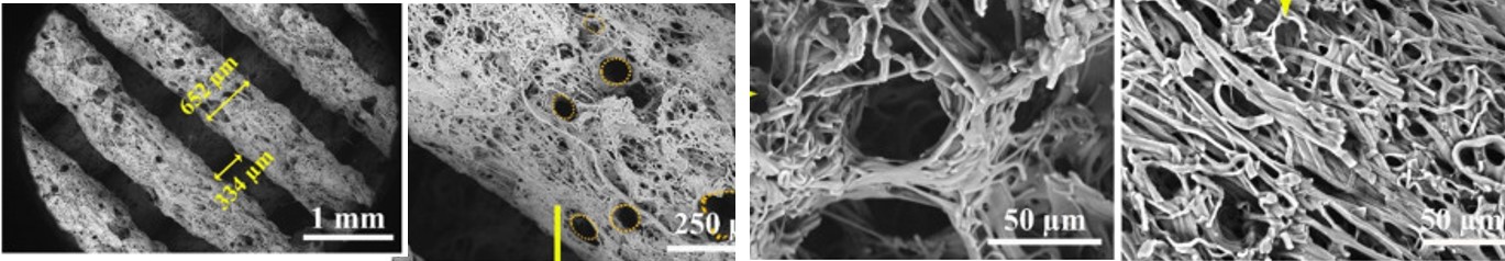
Most studies on the 3D hybrid structure were focused on cell culture performance and characteristics. However, reports of investigation into other properties such as mechanical characteristics are much fewer. Ostrowska et al (2014) checked the compressive modulus of hybrid polycaprolactone microfiber with electrospun poly(L-lactide) (PLLA) nanofiber interlayers (5.4 MPa) and found that it is much smaller than just polycaprolactone microfiber alone (25.2 MPa). Inspection of the hybrid structure found that there were spaces between nanofibrous membrane and the microfibers layer which may contribute to the lower compressive modulus. Flattened microfibers were also observed in the hybrid structure while microfiber in the structure without the nanofibrous membrane interlayer showed round cross-section. Greater heat retention by the relatively thick nanofibrous membrane (thickness of 240 µm) when the microfiber was extruded may have led to slower solidification of the microfiber which results in its flattening.
In more complex structures, multiple steps may be required to form the end desired form. For the repair of an aortic arch, Mayoral et al (2022) used a hybrid fused deposition modeling (FDM) and electrospinning techniques to construct 2D circular patches which were subsequently reshaped using another 3D printed mold specific to the patient's anatomy. FDM in the hybrid scaffold consisted of a thick grid to provide support and to maintain the final shape. The electrospun nanofiber network fills in the space between the grid and to mimic the extracellular matrices (ECM). Polycaprolactone (PCL) was the material of choice for both FDM and electrospinning as it is known to be biocompatible and it has a low melting point.
Rapid prototyping and electrospinning has been used in combination to create application specific structures. Mayoral et al (2022) used a combination of 3D printing and electrospinning for the production of the vascular patch. 3D printing has the advantage of forming a scaffold with a definite shape. Mayoral et al (2022) built the shape of the patch based on the CT scan of a patient's aorta. Fused deposition method with polycaprolactone (PCL) was used to form the patch with four-layered grid pattern design. To deposit electrospun fibers on the 3D printed patch, the collector was given a negative high voltage to direct the electrospinning jet to the collector while a positive high voltage was applied to the nozzle for electrospinning. For the surface of the patch that faces the adventitia, a lower density of electrospun fibers were deposited and for the surface that faces the intima, a higher density of electrospun fibers were deposited. The lower fiber density surface would have greater pore size to allow seeding and migration of mesenchymal stem cells (MSCs) while the high fiber density surface would have smaller pore size to prevent MSCs from falling through while having the porosity for diffusion of nutrient and oxygen through the wall.
Published date: 26 August 2012
Last updated: 05 September 2023
▼ Reference
-
Chen W, Xu Y, Liu Y, Wang Z, Li Y, Jiang G, Mo X, Zhou G. Three-dimensional printed electrospun fiber-based scaffold for cartilage regeneration. Materials & Design 2019; 179: 107886.
Open Access
-
Kim G, Son J, Park S, Kim W (2008) Hybrid Process for Fabricating 3D Hierarchical Scaffolds Combining Rapid Prototyping and Electrospinning. Macromol. Rapid Commun. 29, 1577-1581.
-
Lee H, Kim G H. Enhanced cellular activities of polycaprolactone/alginate-based cell-laden hierarchical scaffolds for hard tissue engineering applications. Journal of Colloid and Interface Science 2014; 430: 315.
-
Mayoral I, Bevilacqua E, Gómez G, Hmadcha A, González-Loscertales I, Reina E, Sotelo J, Domínguez A, Pérez-Alcántara P, Smani Y, González-Puertas P, Mendez A, Uribe S, Smani T, Ordoñez A, Valverde I. Tissue engineered in-vitro vascular patch fabrication using hybrid 3D printing and electrospinning. Materials Today Bio 2022; 14: 100252.
Open Access
-
Mendoza-Buenrostro C, Lara H, Rodriguez C. Hybrid fabrication of a 3D printed geometry embedded with PCL nanofibers for tissue engineering applications. Procedia Engineering 2015; 110: 128.
Open Access
-
Moroni L, Schotel R, Hamann D, de Wijn J R and van Bliiterswijk A (2008) 3D Fiber-Deposited Electrospun Integrated Scaffolds Enhance Cartilage Tissue Formation. Adv. Funct. Mater. 18 53-60.
-
Martins A, Chung S, Pedrp AJ, Sousa RA, Marques AP, Reis RL and Neves NM (2009) Hierarchical starch-based fibrous scaffold for bone tissue engineering applications. J. Tissue. Eng. Regen. Med. 3 37-42
-
Ostrowska B, Jaroszewicz J, Zaczynska E, Tomaszewski W, Swieszkowski W, Kurzydlowsk K J. Evaluation of 3D hybrid microfiber/nanofiber scaffolds for bone tissue engineering. Bull. Pol. Ac.: Tech 2014; 62: 551.
Open Access
-
Park SH, Kim TG, Kim HC; Yang DY, Park TG (2008) Development of dual scale scaffolds via direct polymer melt deposition and electrospinning for applications in tissue regeneration. Acta Biomater. 4 1198-1207
-
Qiu B, Chen X, Xu F, Wu D, Zhou Y, Tu W, Jin H, He G, Chen S, Sun D. Nanofiber self-consistent additive manufacturing process for 3D microfluidics. Microsyst Nanoeng 2022; 8: 102.
Open Access
-
Rivera M L, Hudson S E. Desktop Electrospinning. A Single Extruder 3D Printer for Producing Rigid Plastic and Electrospun Textiles. CHI 2019, May 4-9, 2019, Glasgow, Scotland UK.
Open Access
▲ Close list

 Electrospun membrane inserted into periodic layers of fuse deposited microfiber layers [Ostrowska et al 2014. Journal of Nanomaterials, Bull. Pol. Ac.: Tech 2014; 62: 551. This work is licensed under a