This SOP describes the method of testing of electrospun fiber membrane to determine its tensile strength and deformation characteristic. It includes method of peeling membrane off the collector and sample preparation for mechanical testing and determination of its dimension.
Disclaimer
Any instruments and materials mentioned in this standard is for reference only. Electrospintech does not guarantee its availability or quality.
This standard did not undergo formal peer review process and is for reference only.
This standard does not address all safety and health issues regarding the performance of the experiment and/or the end product if any. It is the responsibility of the user to establish appropriate controls, safety and health practices. Local regulatory controls and limitation shall be addressed by the users of this standard prior to its use.
An applicable standard for tensile testing of nanofibrous membrane is ASTM D882 - 10 Standard Test Method for Tensile Properties of Thin Plastic Sheeting. This standard cover tensile testing of plastic films that is less than 1 mm of thickness which is applies to most electrospun nanofibrous membrane.
1. Introduction
In electrospun membrane, its mechanical property is determined by the arrangement and packing characteristic of the nanofibers that made up the membrane. As the electrospinning process is influenced by various inter-related and independent variables, minute differences in the collection of the membrane may result in changes in the packing characteristic of the fibers which will in turn influence its failure mechanism. For thin or treated membranes, it is likely that it will fail through necking and catastrophic failure at a maximum load. However, in thicker membrane, it is likely that it is made out of several thin layers of fibers and its failure will be through delamination of the individual layers. Therefore, it is advisable to perform mechanical testing of the membrane when electrospinning conditions have been altered or its dimensional specification has changed.
2. Equipment and consumables
2.1 Electrospinning apparatus
The electrospinning setup may be procured (See http://electrospintech.com/espin-supplier.html) or self-assembled (See ES1001, http://electrospintech.com/SOP-ES1001.html).
2.2 Collector
Most electrospun membranes are constructed by electrospinning on a flat plate collector. Depending on the fiber membrane characteristic, the membrane may or may not be easily taken off the flat plate collector without damaging the membrane at the collector interface.
Generally, it is easier to peel the membrane off the collector surface immediately after spinning. However, if this is not possible, the following techniques that may be used to facilitate separating the fiber membrane from the collector surface
2.2.1 Non-stick surface
A layer of Teflon coating may be applied on the surface of the collector. This potentially creates a non-stick surface that faciliates membrane removal.
2.2.2 Separating medium
A separating medium such as gelatin, alginate or oil may be applied to the surface. In case of water soluble separating medium such as alginate, the membrane deposited on the substrate may be soaked in water to peel off the membrane.
2.2.3 Water surface collector
Electrospinning and deposition of the fibers on water. Electrospun fibers generally float on water and the membrane can simply be lifted off the water surface.
2.3 Specimen preparation
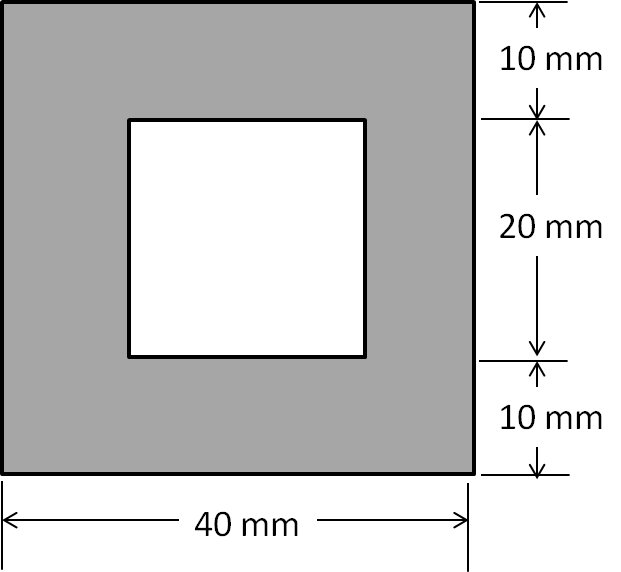
A test window frame is used to hold the membrane and prevent unwanted stretching of the membrane prior to testing. The dimension of the test frame is shown in figure 1. A smaller piece of the tab is used to sandwich the membrane in between. Epoxy glue may be used to secure the membrane to the tabs.
Note: Test specimen with longer gauge length may be more likely to fail through separation of fiber layers. Too short a gauge length may result in failure propagation into the tab resulting in inaccurate result.
Figure 1. Window frame made of paper board or plastic sheet to form the tab for tensile testing.
2.4 Dimension determination
A micrometer screw gauge may be used to determine the thickness of the membrane. However, since nanofibrous membrane is porous and generally soft, care must be taken to ensure that the membrane is not compressed during measurement. The contact surface of the measuring jaw for taking diameter measurement may be increased using flat and rigid tabs (eg. Glass tab) to reduce or prevent compression.
If the membrane is found to be compressed, alternative method of thickness determination may be necessary.
Contactless measurement equipment such as laser and ultrasonic thickness gauge may be used if available.
3. Procedures
3.1 Tensile testing
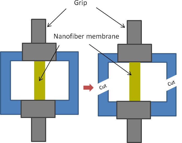
Mount the test specimen (test window frame with the fiber) on the tensile tester such that the grip is on the tabs holding the fiber membrane.
Cut off a portion of the window frame as shown in the figure 2.
Figure 2. Cutting of vertical ribs of frame prior to start of tensile test.
Ensure the setting on the tensile tester is correct and start the test.
Recommended setting:
Specimen dimension: 40 x 10 mm
Gauge length: 20 mm
Strain rate: 5 mm/min
Load cell: 100 N
Note: Breakage load of membrane should be at least 5% of load cell . Refer to manufacturer's product specification.
See Appendix A for summary of tensile test settings found in literature.
3.2 Acceptance criteria
Only test sample that failed at least 2 mm from the edge of the tab shall be included in the test result
Chen D W C, Liao J Y, Liu S J, Chan E C. Novel biodegradable sandwich-structured nanofibrous drug-eluting membranes for repair of infected wounds: an in vitro and in vivo study. International Journal of Nanomedicine 2012; 7: 763.
Forouhardshad M, Saligheh O, Arasteh R, Farsani R E. Manufacture and Characterization of Poly (butylene terephthalate) Nanofibers by Electrospinning. Journal of Macromolecular Science 2010; 49: 833.
Junkasem J, Rujiravanit R, Supaphol P. Fabrication of a-chitin whisker-reinforced poly(vinyl alcohol) nanocomposite nanofibres by electrospinning. Nanotechnology 2006; 17: 4519.
Kim Y H, Min Y K, Lee B T. Fabrication and material properties of fibrous PHBV scaffolds depending on the cross-ply angle for tissue engineering. J Biomat. App. 2012
Luong N T H. Engineered Poly(L-lactic acid)-based nanofibers for osteogenic differentiation of human and mesenchymal stem cells. PhD Thesis. NUS 2012.
Ojha S S, Afshari M, Kotek R, Gorga R E. Morphology of Electrospun Nylon-6 Nanofibers as a Function of Molecular Weight and Processing Parameters. J. Appl. Polym. Sci. 2008; 108: 308.